|
ZB74-bus SIO/2 Serial Comm. Board |
|
PCB Circuits (click to enlarge) |
|
|
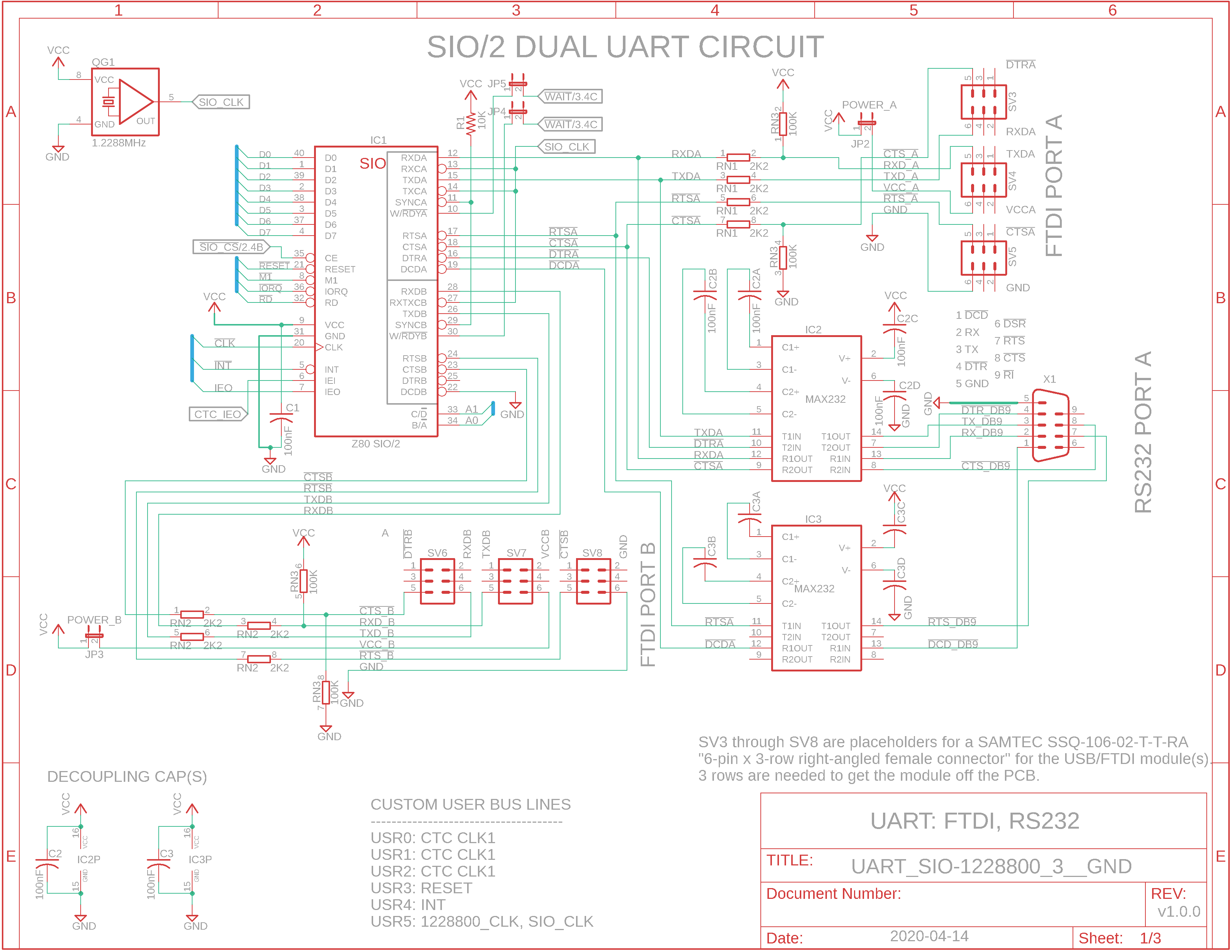
Eagle CAD: 1. SIO/2 UART Serial Circuit
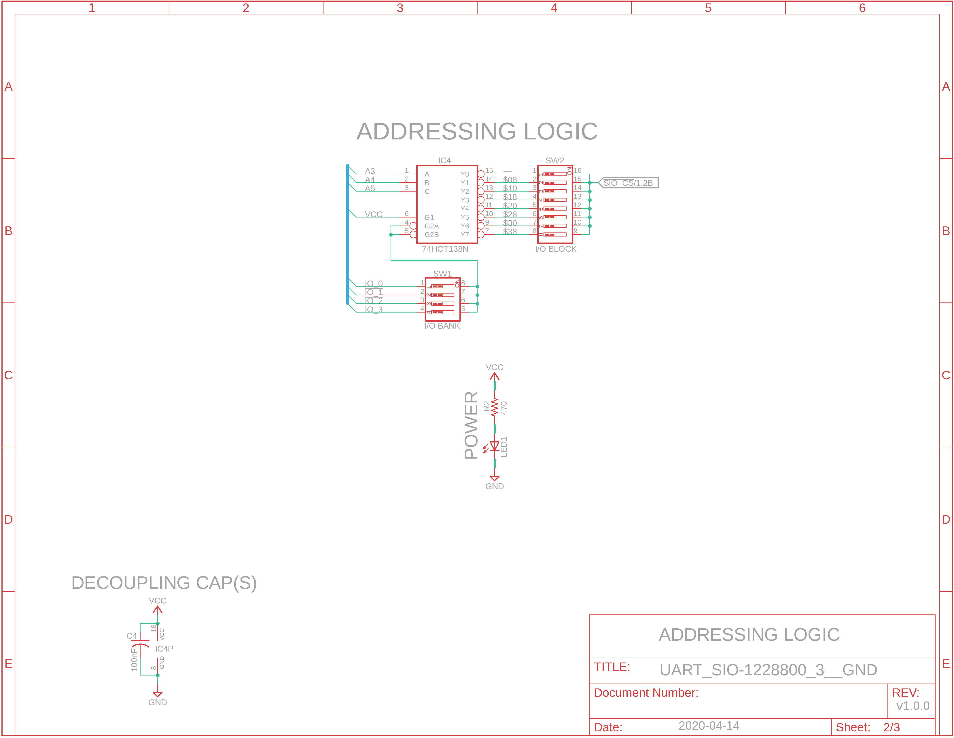
Eagle CAD: 2. Addressing Circuitry
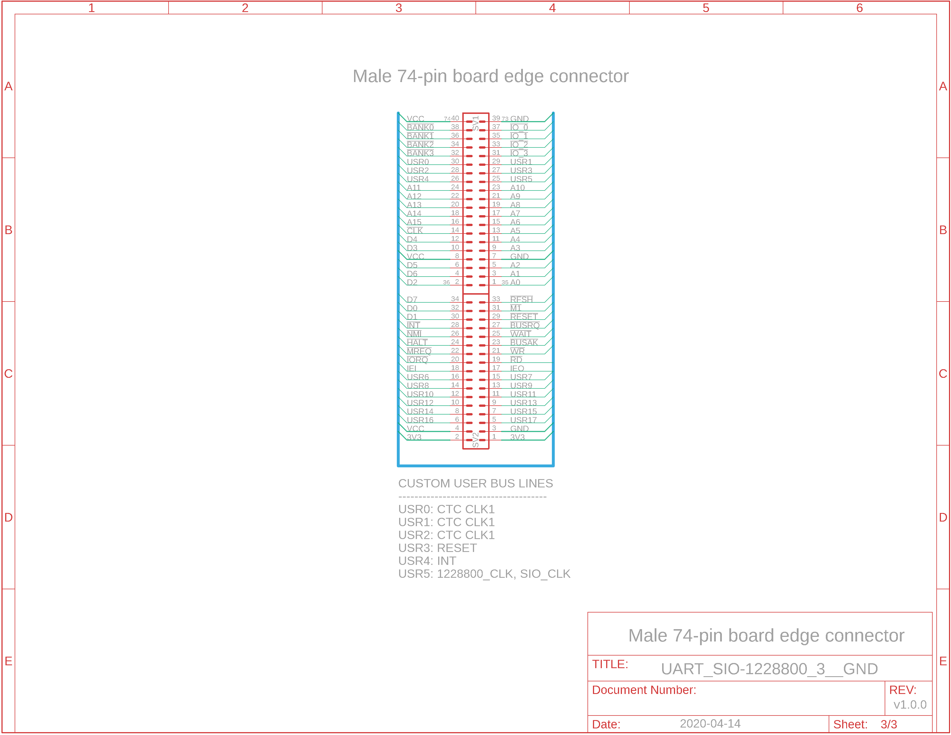
Eagle CAD: 3. Board Edge Connector
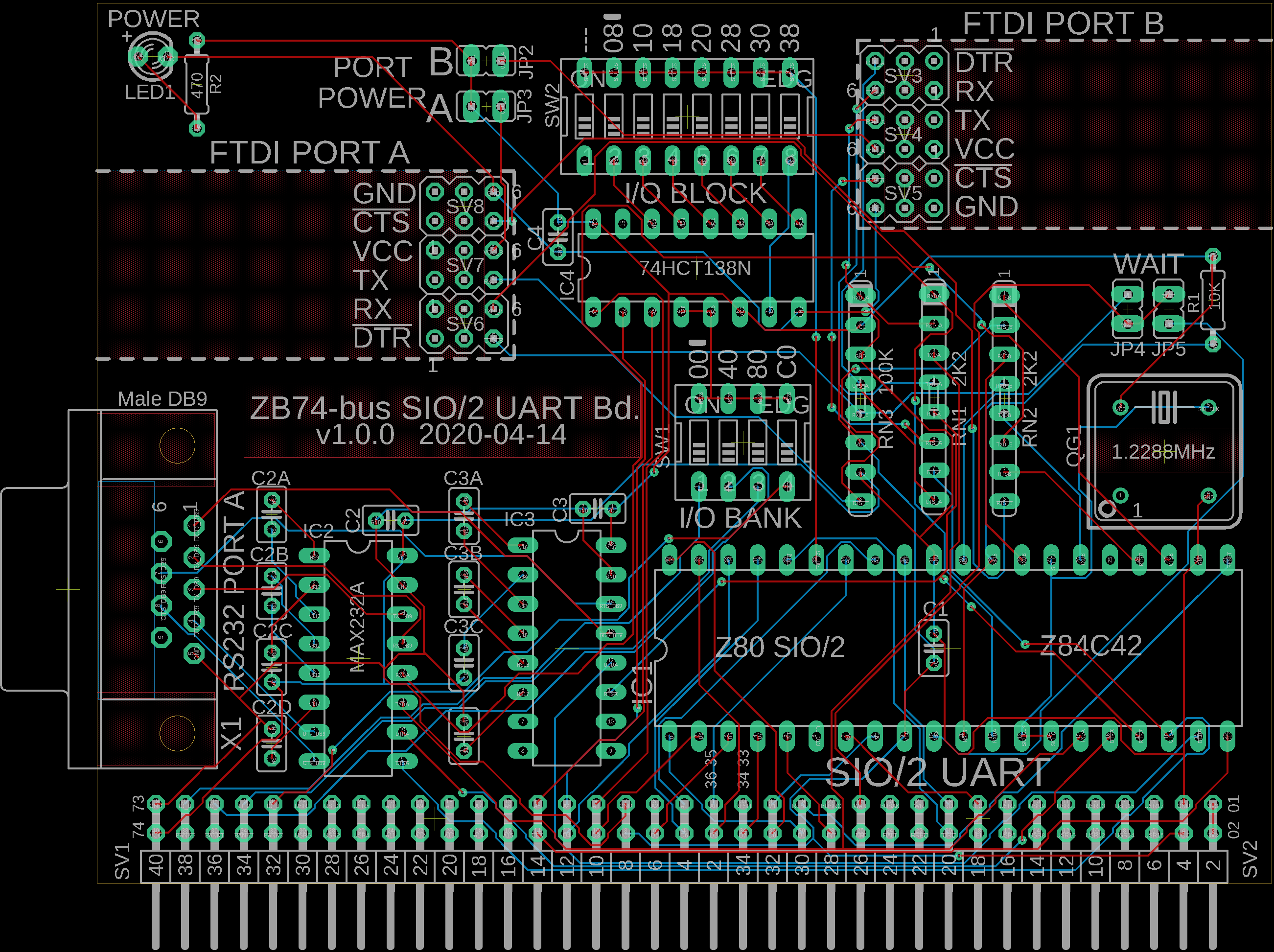
Eagle CAD: 4. Possible PCB Layout
(Bill of Materials) |
PLEASE NOTE: I do not sell production boards. If you would like to buy an M62 Z80 system board/parts kit, contact Peter Murray, Peter@39k.ca I simply provide you with information to build your own breadboard computer.
Overview In SBC2, we used a 16C550 UART in polled mode. This time we'll try the original Zilog Z80 SIO/2 dual UART in both Polled and Interrupt modes. The 16C550 UART does not support Interrupt Mode 2 unless you're willing to add more hardware like a '573 latch. The SIO/2 being a Zilog device does support several interrupt modes as well as Interrupt Daisy Chaining. It does not, however, have an internal mechanism for providing a serial clock so we'll connect a separate crystal oscillator. Alternatively, you can use the CTC board to create the frequency(s) you need.
Comm Ports: USB/FTDI and DB9/RS232 The RS232 ports will be connected to an inexpensive USB/FTDI module called the FT232RL. This will be through 2K2 current-limiting resistors. Without the resistors the FTDI module will try to use both VCC and the TX line to power your Z80 system. This happens when the backplane power is removed via the power switch but the USB/FTDI module is still connected via a USB cable to your PC. It will try to power the system which will eventually burn out the module as I have found out - twice! (On the UART Comm Board PCB there is a jumper labeled PORT POWER on the VCC line so you can disable it you wish.) Note that the RX line will continue to work if you cook the USB/FTDI module (you'll see the BIOS screen when you reset the SBC but that's all - no keyboard input will be accepted). I don't trust the longevity of these cheap off-shore USB/FTDI devices so I changed the design to include a 3 tier right-angled female header to which you attach the module. The module stays within the board area with only the cable sticking out. If the module fails, you can easily replace it. Three tiers was necessary (you plug into the top row of the three rows) to get enough support strength and clearance off the PCB. No signal traces run under the area used by the module. You plug the USB/FTDI module into the female header which will keep it parallel to the PCB and less obtrusive. The RS232 port is also connected to a MAX232A transceiver IC and a male DB9 connector. Only the 4 essential signals (TX, RX, output DTR, input CTS) are ported. If you want more signals like DCD (data carrier detect) then you're prob'ly going to have to add another MAX to your design to carry the additional signals. The 4" x 3" (102mm x 76mm) board has the room but do you really need them for your application?
Programming the SIO/2 UART for interrupts Our initial design for SBC and SBC2 used the polling method: check if a character is in the buffer either to be sent or having been received, and process it. It works well but it's not the most efficient. This time we'll use interrupts to inform us and process the data appropriately. Note that although the SIO/2 is a dual UART, we'll code for just channel A.
I see the schematics. Where is the Bill of Materials parts list? The BOM is at the bottom of the adjacent panel.
How big is the SBC and what will the printed circuit board look like? The UART PCB measures 4" wide x 3" high. Click on the adjacent thumbnail to see a possible parts layout. Some of you may notice the PCB connector is similar to the RC2014 but the bus layout is not. This layout is new whereas the RC2014 has been adapted many times over the last several years.
Note: M62 Bus is copyrighted by Peter Murray of Murray Electronics, http://www.39k.ca |
![]()
Tags: SIO/2 UART, Z80 MBC, Z80 1MB memory