|
SIO/2 UART Info 1 |
| Resources (click to enlarge) | |
|
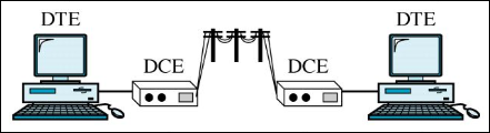
RS232 Point-to-Point Network
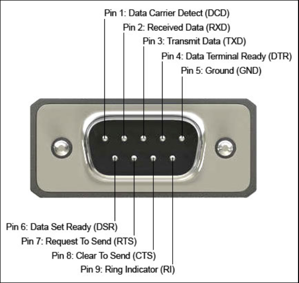
RS232 Male DB9 Pinout
|
RS232 Jargon & Comm Signals DTE is data terminal equipment, the user terminal/PC or host. DCE is data communication equipment, the modem attached to the terminal/PC/host.
Some of the RS232 signal lines can be asserted to a specific level (high or low) to accommodate a USB/FTDI module or attached modem, but that does not mean they will function as originally specified in the RS232 spec. This Maxim link will provide you with a brief history of the RS232 spec.
DTR Data Terminal Ready - Output signal from DTE to DCE. Presence indicator. "I am here."
DSR Data Set Ready - Input signal from DCE to DTE: Presence indicator. "I am here."
RTS Request To Send - Output signal from DTE to DCE. Hardware flow control. "If low, send to me. If high, stop sending to me."
CTS Clear To Send - Input signal from DCE to DTE. Hardware flow control. "If low, send to me. If high, stop sending to me."
RI Ring Indicator - Input signal from DCE to DTE. - CD indicates a ringing signal from the telephone line has been detected by the modem
DCD Data Carrier Detect - Input signal from DCE to DTE. - DCD indicates carrier signal has been detected by the modem |
|
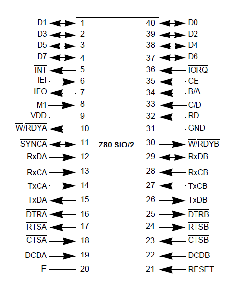
SIO/2 DIL40 Pinout
SIO/2 Functions
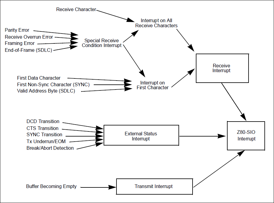
SIO Interrupt Structure
|
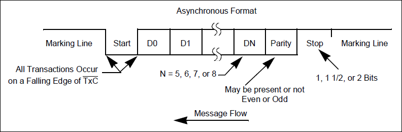
Async Operation Asynchronous data in the transmit shift register is formatted with start and stop bits and is shifted out to the transmit multiplexer at the selected clock rate.
Clocking To clock data bus in from the CPU, the 4MHz CPU CLK signal will be connected to the SIO/2 at the CLK input. The SIO/2 does not have its own baud rate generator like the 16C550 UART. To produce a 57600bps Tx or Rx data rate, we'll connect a 1.8432MHz crystal oscillator to both the UART A and B channels via RxCA, TxCA and RxTxCB, and set the clocking rate at 32x: 57,600 x 32 = 1,843,200bps. We could also set it at 115,200bps with a 64x clocking rate. Our character formatting will be 8N1: 8-bit character, No parity, and 1 Stop bit. For the most flexibility, we'll use Interrupt Mode 2 that supports multiple interrupt service routines (ISRs) if desired.
Character Formatting To receive or transmit data in the Asynchronous mode, the Z80 SIO/s must be initialized with the following parameters: - character length - clock rate (raw input rate is divided by 1, 16, 32, or 64 to get data rate) - number of stop bits - even, odd, or no parity - interrupt mode - receiver or transmitter enable. No data flows until the Transmit Enable bit is set
In the diagram above and reading from the left, note how the serial line is normally marking (high) when no data is being sent. The first "space" (low) is the Start bit and the last "mark" (high) is the Stop bit as the serial line returns to marking.
The parameters are loaded into the appropriate Write registers by your program. WR4 parameters should be issued before WR1, WR3, and WR5 parameters or commands. WR6 and WR7 registers are not used with Async mode.
Poll/Interrupt The Z80 SIO offers the choice of Polling, Interrupt (vectored or nonvectored), and Block Transfer modes to transfer data, status and control information to and from the CPU. Transmit interrupts, Receive interrupts, and External/ Status interrupts are the main sources of interrupts. - Each interrupt source is enabled under program control with Channel A having a higher priority than Channel B, and with Receiver, Transmit, and External/Status interrupts prioritized in that order within each channel. Although the receiver can interrupt the CPU in one of three ways, we'll focus on "Interrupt on all receive characters". - The main function of the External/Status interrupt is to monitor the signal transitions of the CTS, DCD, and SYNC pins. However, an interrupt is also caused by a Transmit Underrun condition or by the detection of a Break (Asynchronous mode). |

![]()
Tags: Z80 MBC, 1MB memory