|
SIO/2 UART Interrupts |
|
<= Poll 3 Interrupts 1 => |
|
SIO/2 Interrupt Priority The SIO/2 has two UART channels with Channel A having a higher priority than Channel B. The main sources of Z80 SIO/2 interrupts are prioritized as: - Receive Interrupt: an interrupt can be generated if a character is received into the receive buffer. Reading the channel data register will empty the buffer and remove the source of the interrupt. Issuing RETI will reset the hardware interrupt request - Transmit Interrupt: an interrupt can be generated if a character was transmitted and now the transmit buffer is empty. Issuing the value 28h, Reset Tx Interrupt Pending, will clear the interrupt and allow the next Tx character to be sent to the SIO - External/Status Interrupt: an interrupt can be generated if there are signal transitions of the Clear To Send (CTS), Data Carrier Detect (DCD), and (SYNC) pins
Adding More Interrupts When programmed to do so (Channel B/register WR1/bit D2), the SIO can modify 3 bits of the interrupt vector in the status register (RR2) so that it points directly to one of 8 interrupt service routines (ISRs) in memory, thereby servicing conditions in both channels.
Interactive versus Block Transfer "Interrupt on First Received Character" is typically used with block-transfer mode. We'll use "Interrupt On All Received Characters" mode instead for typical interactive use.
Z80 Interrupt Modes and the IVT Z80 Interrupt Mode 2 (IM2) uses any 16-bit address for the Interrupt Vector Table (IVT) unlike the other three (0, 1, NMI) 8-bit interrupt modes which are confined to the first 0100h bytes of memory. The Interrupt Register (IR) holds the high byte and the peripheral device (SIO/2) interrupting the CPU holds the low byte of the 2-byte address. This address is the start of the Interrupt Vector Table. The IVT contains the "jump to addresses" of the Interrupt Service Routines (ISRs). If all 8 ISR addresses have been sequentially placed in the table, the first 2-byte address points to the first of the eight ISRs. The second 2-byte address points to the second ISR, etc. The eight ISRs can be placed anywhere in memory thanks to their 2-byte pointers in the IVT.
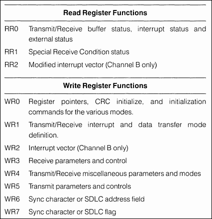
Internal Structure Each channel contains its own set of control and status (write and read) registers, and control and status logic that provides the interface to modems or other external devices. The registers for each channel are designated as follows: - WRO to WR7: Write Registers 0 through 7 (WR2 is found in Channel B only.) - RRO to RR2: Read Registers 0 through 2 (RR2 is found in Channel B only.) Channel B contains Write Register 2 (WR2) that holds the lower byte of the start of the Interrupt Vector Table (IVT); the Interrupt Register (IR) contains the upper byte. Channel B contains Read Register 2 (RR2) that is used to show all 8 interrupts if enabled via ChB/WR1/Bit2.
Register Functions
Programming The system program first issues a series of commands that initialize the basic mode of operation and then issues other commands that qualify conditions within the selected mode. Example: - Async transfer mode - Character format (8N1) - Interrupt mode if any - Rx and Tx enable
|
|
<= Poll 3 Interrupts 1 => |
![]()
Tags: Z80 MBC, 1MB memory