|
SIO/2 UART Interrupts 1 |
|
Click to Enlarge |
<= Interrupts Interrupts 2 => |
|
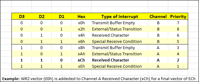
Interrupt Priority List
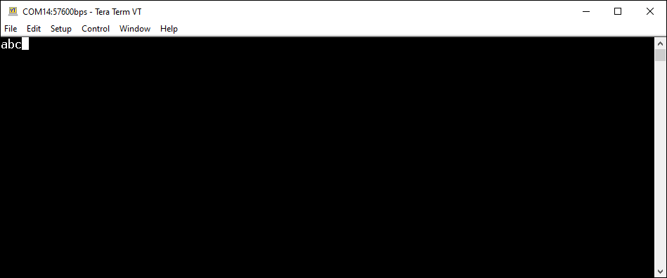
Terminal Emulator Screen
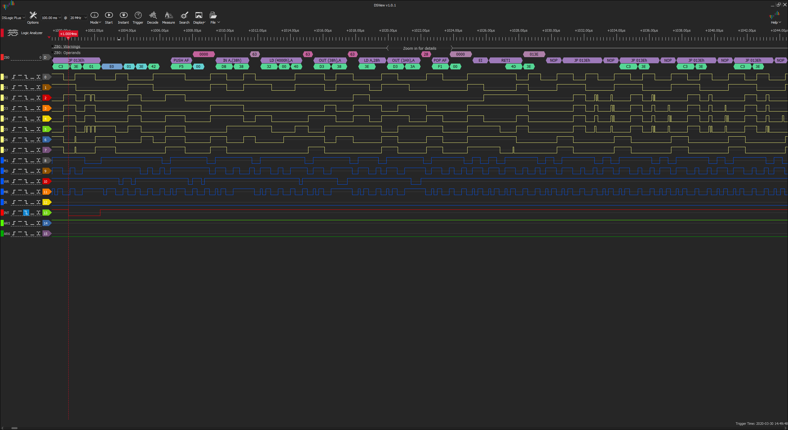
DSLogic+ Logic Analyzer
Screen
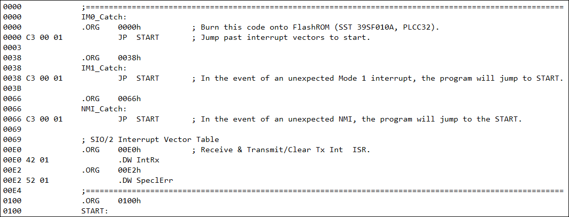
Interrupt Service Routines & Interrupt Vector Table
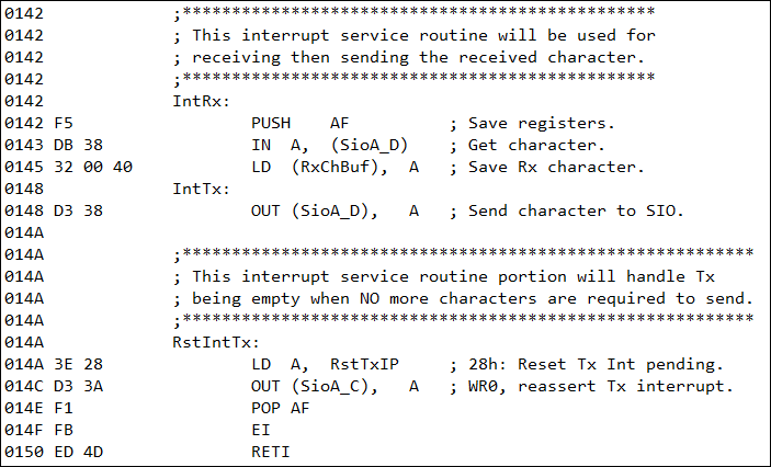
Rx/Tx/ClearTxInterrupts
Interrupt Service Routine Single IM2 Interrupt Demo Program
|
DEMO SINGLE INTERRUPT On this page we'll explain how SIO/2 interrupts work and provide a demonstration program for you to burn into a ROM, or rewrite slightly as a standalone app.
Interrupt Service Routine (ISR) Z80 Interrupt Mode 2 uses 16-bit addresses for its interrupt service routines (ISRs) unlike the other three (0, 1, NMI) interrupt modes which are confined to the first 0100h bytes of memory. The Interrupt Register (IR) holds the high byte and the peripheral device (SIO/2 or CTC, etc.) interrupting the CPU holds the low byte of the 2-byte address. The IR was set to 00h (line 128 of our code) and the WR2 register in Channel B was set to "E0h" (line 104 of our code) using the SIO Channel B Control Register, "SioB_C". The combined 16-bit address is 00E0h in the boot ROM. It could have been placed anywhere in memory but we chose the boot ROM to simplify testing.
Interrupt Vector Table (IVT) "00E0h" is the address of the start of the Interrupt Vector Table (IVT). All IVT entries are 2 bytes in size. "00E0h" is also the address of the table's first entry for the Interrupt Service Routine (ISR) "IntRx". This ISR reads a terminal key press and echoes it to your screen. The second ISR entry in the IVT would be at address 00E2h if we were setup for multiple interrupt vectors. The IVT is essentially a "jump index" to the ISRs. It's important when adding these "jump entries" to the table that the ISRs themselves start on even address boundaries, otherwise things will get weird if they work at all. Just adding a NOP to the previous ISR will even up the starting address of the next ISR. It's the starting addresses of the ISRs that you place in the IVT.
The IVT in our Example If you examine the 4th item from the top in the adjacent panel, you'll see a line that reads "; SIO/2 Interrupt Vector Table". Below this line in the leftmost column is address "00E0". We placed a ".ORG" statement to start the addressing at "00E0". The next line contains the code "42 01" in the second column which is the result of placing the statement ".DW IntRx". This assembler directive will save us having to figure out the location of our first ISR, IntRx. So the first entry in our IVT is "4201" indicating the address of the first ISR is "0142h". Note that it's an even number. As stated above, all of your ISR addresses in the table must be even numbers. For demo purposes we used ".DW SpeclErr" to have the assembler determine where our next ISR is located. This is at location 0152h as you can see. In summary, location "00E0h" contains the "jump to address" (0142h) to our first ISR, and location "00E2" contains the "jump to address" (0152h) to our second ISR.
SIO/2 UART Interrupt Mode 2 Starting with the second object in the adjacent panel, we have the screens associated with an SIO/2 running in Interrupt Mode 2 but with just one interrupt. In this second screenshot a letter was typed in TeraTerm (configured for 57,600bps) and you can see it echoed to the screen. In the third screenshot, DSView Logic Analyzer was setup to trigger on INT going low.
Logic Analyzer (LA) Screen Third from the top in the adjacent panel is the DSLogic+ Logic Analyzer thumbnail. If you click on the link you'll find that it is designed to stay open in a separate browser window so you can <CTRL><Tab> between it and the ISR screenshot (at the bottom of the adjacent panel) as you examine it. Clicking on the LA screen should reveal a red, dashed vertical line on the left that denotes the low-going trigger set on the bus' INT line. The CPU was in the middle of a "JP 013Eh" instruction when the interrupt occurred. To the right of the instruction you can read "E0" which is the low byte of the ISR's 16-bit address. This is what the SIO/2 puts on the data bus for the CPU to combine with the high byte of the IR to yield the complete IVT address, 00E0h. The "01 3E" that follows is the current address being pushed onto the stack. You can tell that's so because it's not in byte-reversed Little Endian format. "42 01" follows but you cannot see the "01" - it's missing although you could still read data lines D7 to D0 to realize it's "01" . "01 42" is the location of the ISR found in the IVT that the CPU will jump to now. The next bytes you read should match the ISR itself, byte for byte, starting in line 141 of the program. If you look above the LA's code to the timeline, you can see the "EI" and "RETI" instructions around 1026uS. These denote the end of the ISR. Above and to the right of the "RETI" is the return address of "013E" that was pushed on the stack earlier. At this point the system returns to the endless looping.
Only One Interrupt If you choose to write only one interrupt as we have done above, then it would have to contain all of the needed functions. Alternatively, you can use multiple Interrupt Mode 2 interrupts by enabling the Channel B WR1-D2 bit.
|
|
<= Interrupts Interrupts 2 => |
|
![]()
Tags: Z80 MBC, 1MB memory