|
SIO/2 UART Interrupts 2 |
|
|
<= Interrupts 1 Interrupts 3 => |
|
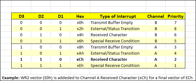
Interrupt Priority List
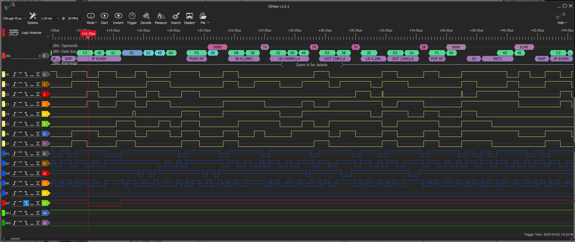
Logic Analyzer View of Multiple Interrupts
|
DEMO MULTIPLE INTERRUPTS Interrupt Bits The register bits that affect interrupts are WR0-D5 to D3 and WR1-D4 to D0. There are 8 different interrupt vectors that the SIO can automatically put on the Z80 data bus. They are formed from the single vector written in the initialization phase of the SIO (as well as enabling ChB WR1 Bit 2). We'll use the value "E0h" in our code as the start of our Interrupt Vector Table (IVT).
Forming the eight 16-bit Interrupt Mode 2 Vectors For the eight vectors to be formed, WR1-D2 (Status Affects Vector) bit will need to be set to a 1. If this bit is set and interrupts are enabled, then the type of interrupt will modify specific bits of the WR2 interrupt vector that is sent on the data bus to the CPU. Those bits are WR2-D3 to D1 and they give us our 8 interrupt permutations, four for each channel. You can see them at the top of the adjacent panel in the Interrupt Priority List. If you did not set the WR1-D2 (Status Affects Vector) bit to 1, you would have only one interrupt vector. That was shown in our single interrupt example on the previous page; the IVT was set for location 00E0h and contained only one useable entry.
Interrupt Priority List According to the Interrupt Priority List, the "Received Character" interrupt vector has an address of "xCh". Counting down from the top of the list, this would become the seventh entry in the IVT. With our Interrupt Vector Table starting at E0h and each table entry occupying 2 bytes, we know we need to place a "jump to address" at the seventh location. (The proper name for the "jump to address" is ISR Vector.) The first location would be at E0h, the second at E2... and the seventh at ECh. In summary, this seventh entry in the IVT would be the start address of the Interrupt Service Routine (ISR) to handle the Received Character interrupt.
Logic Analyzer View If you examine the second item in the adjacent panel you'll see a Logic Analyzer capture of an interrupt occurring. Behind the red, vertical dashed line that denotes the INT line going low you should see "Z80: Operands", "Z80: Data bus", etc. (the obscured lines are Z80: Instructions and Z80: Warnings). We see the purple instruction "JP 014E" and then to the right but above it we see the blue data bus value "EC". The JP instruction is what the CPU was processing when the interrupt occurred. If you consider that our WR2 interrupt vector is "E0h" and a type of interrupt was added to it to give us the value "ECh", then we have to conclude a "Received Character" interrupt in Channel A occurred: E0h + xCh = ECh. And that is what happened: we pressed the letter "p" which has an ASCII value of "7Ah" that you can see in the pinkish/purple (mauve?) decode.
Show Me The Code SIO_Interrupt_08a_CHA.zip contains the code, binary and list files you'll need to test the multiple interrupts configuration of the SIO/2. We recommend you burn it into a FlashROM. |
|
<= Interrupts 1 Interrupts 3 => |
|
![]()
Tags: Z80 MBC, 1MB memory