|
SIO/2 UART Interrupts 4 |
|
INFO |
<= Interrupts 3 Interrupts 5 => |
|
On the previous page we: - set up the environment constants
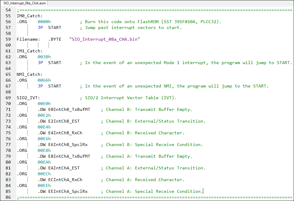
Now we'll add the assembly code to specify the general interrupt vectors as well as the eight additional interrupts for the Status Affects Vector configuration.
The IVT is at 00E0h and so it the first IVT vector. We used the assembler directive of ".DW" so we would not be burdened with determining the address of the actual interrupt service routine (ISR).
There are 3 screenshots in the adjacent panel.
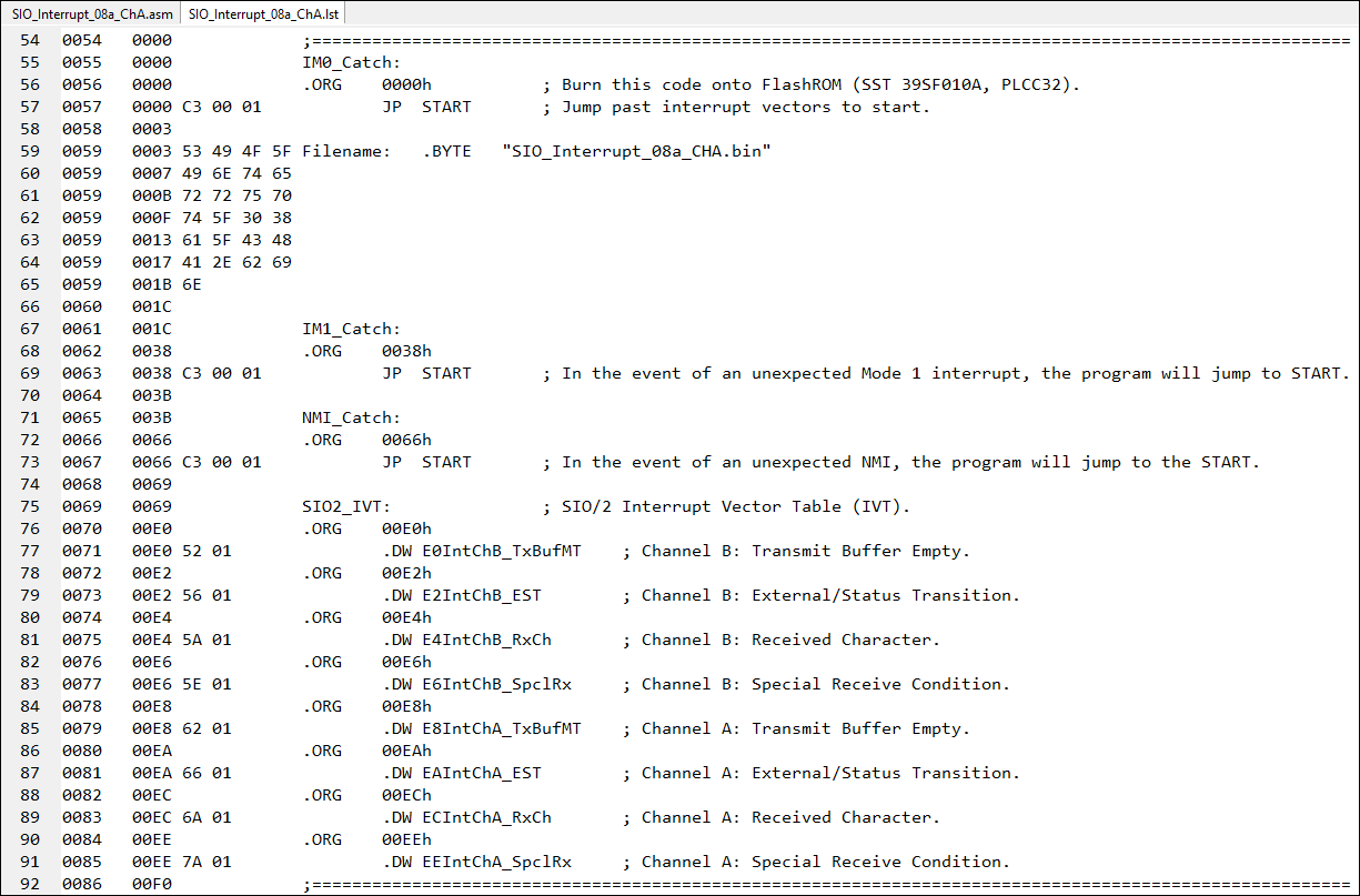
If we examine the .lst file in the middle, you can see that adjacent to the directive ".DW E0IntChB_TxBufMT" is the value "52 01". If we reorient the little-endian data, we get the address "0152" which is where we will actually find the interrupt service routine.
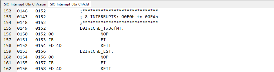
Check out the bottom screenshot where you should find the short interrupt service routine that contains: NOP EI RETI
This is "filler" for our ISR placeholder until we write a real ISR. We'll examine a real ISR shortly. |
General Interrupt Register Vectors and Interrupt Vector Table (IVT)
|
|
<= Interrupts 3 Interrupts 5 => |
|
![]()
Tags: Z80 MBC, 1MB memory