|
SIO/2 UART Interrupts 5 |
|
Info |
<= Interrupts 4 Interrupts 6 => |
|
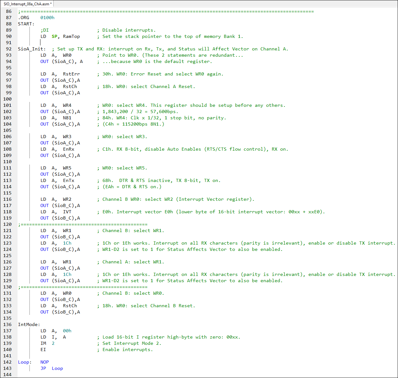
On the previous page we setup: - environment constants - Interrupt Vector Table config
Now we'll add the assembly code to configure the Write registers.
The WR2 register is in channel B, not in channel A. That is why we sent the command to use "E0" as the start of our IVT to channel B control instead of to channel A control. You can find this at line 116.
Further down in the code you'll see two separator lines that border two code chunks; they are the same instructions except that the upper chunk is for channel B and the lower chunk is for channel A.
Why? Good question. According to page 280 , even though we are not using channel B (you can see that we reset it in the next code chunk that follows), we had to do it this way because the "Status Affects Vector" function is in the B channel register. That is, the vector provided by the SIO/2 UART to the Z80 CPU would read "E0", not "EC" if a character was received.
|
SIO/2 interrupts
mode: UART registers configuration |
|
<= Interrupts 4 Interrupts 6 => |
|
![]()
Tags: Z80 MBC, 1MB memory