|
CIRCUIT 1-7-1: The CTC Counter/Timer Circuit |
| Name | Resources (click to enlarge) | Info |
|
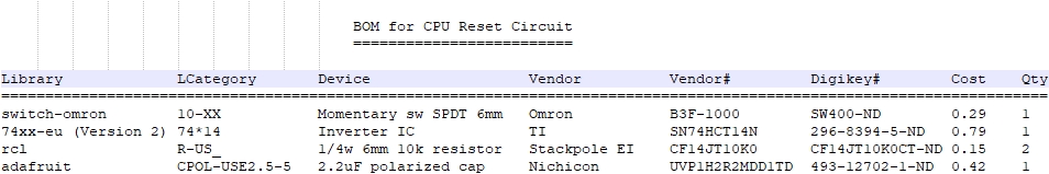
Z80 CTC (Z84C30xx)
(Bill of Materials) |
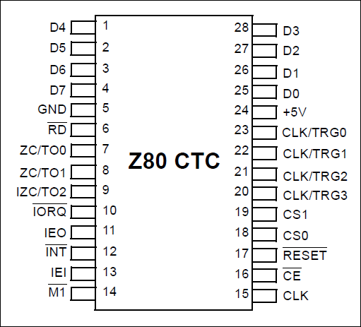
1. CTC DIP28 Pinout
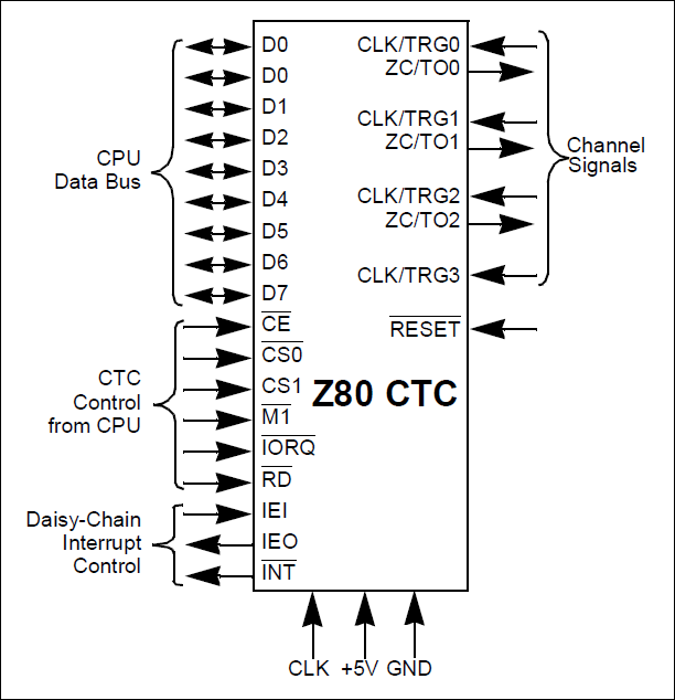
2. CTC Pin Function Groups
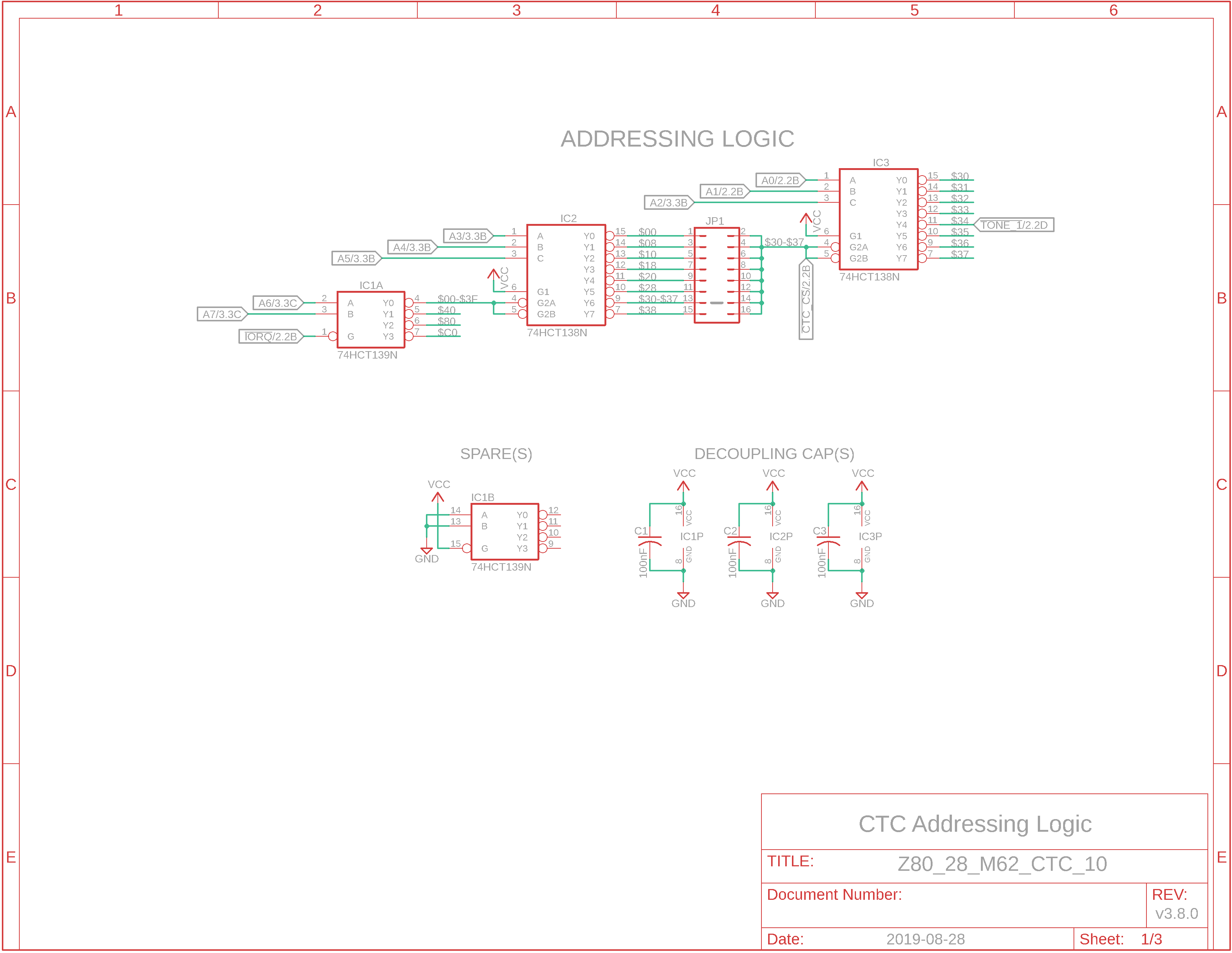
3. Eagle CAD: Addressing Logic
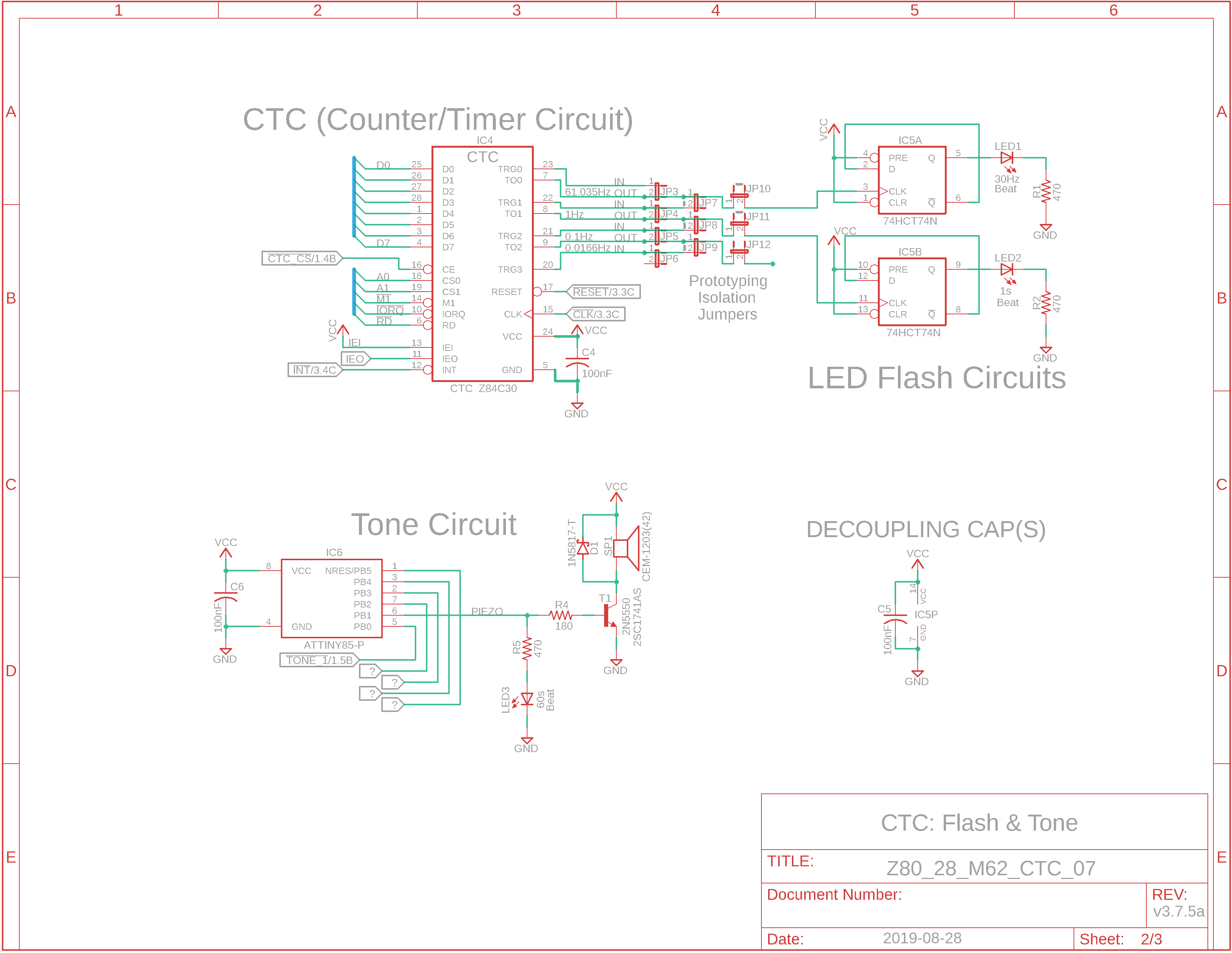
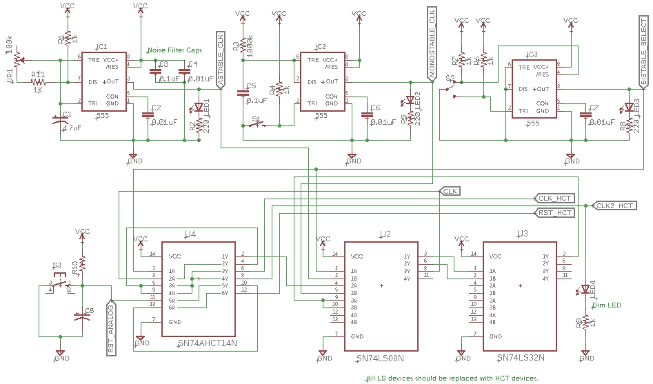
4. Eagle CAD: LEDs & Tone Flasher
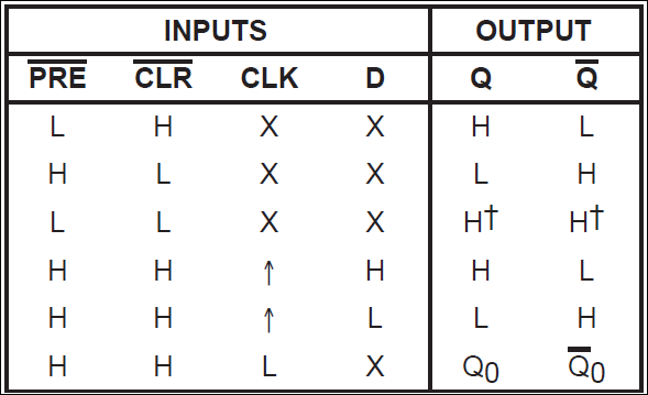
5. 74HCT74 Flip-Flop Function Table
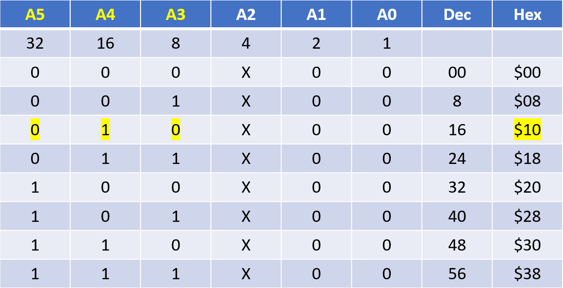
6. Bit Values
7. 74138 Addresses
|
Brief History Back in the day Zilog introduced a number of peripheral IC devices for the Z80 which all supported the Z80's interrupt handling system and I/O address space. These included the CTC (Counter/Timer Circuit), the SIO (Serial Input Output), the DART (Dual Asynchronous Receiver Transmitter), the PIO (Parallel Input-Output), and the DMA (Direct Memory Access) Controller.
What is a CTC? The Z80 CTC is a 4-channel counter/timer peripheral chip for the very successful Z80 8-bit microprocessor, available primarily in a 28-pin dual-in-line package DIP but also available to be socketed as a PLCC-44.
Application Typical CTC applications include event counting, interrupt and interval counting, and serial baud rate clock generation.
CTC Overview A counter/timer is a peripheral device that can count input channel signals or countdown from a specific time value. The Zilog CTC (Z84C30xx) has 4 programmable timers that can be run by the Z80 system clock or by an external clock on the corresponding CLK/TRG channel input pin. If any of the 4 channels is using an external clock input it can act as a counter. We can use a Timer to tell the Z80 to execute a specific subroutine once a period of time has elapsed. Additionally, it can raise an Interrupt to the Z80 CPU after receiving a specific number of input pulses. Another ability would be to generate a specific signal frequency on a pin, perhaps a clock signal to a UART like the Z844x SIO/2, Z8470 DART, or Ti PC16C550d UART. This would save the cost and board space of having to add a crystal resonator like the 1.8432MHz that is commonly used with UARTs.
A CTC usage example Let's say that if we wanted a 57,600bps data rate for a UART, we would have to multiply that value by 16 (the UART sampling rate) to get the UART "multiplier integer"; the sample rate would be 921,600Hz. If we then multiplied the sample rate by 8, we would arrive at 7.3728MHz. (This is a common and cheap crystal to purchase.) So our multiplier would be 8 that we would configure within the UART. If we wanted our UART to communicate twice as fast (115.2Kbps), then our UART multiplier would be half or 4. So far we have not needed the CTC - the UART is doing all the work with a cheap external crystal. You can find a lot more info about UART configuration here in the Circuits section.
Another CTC usage example What if we wanted to halve the crystal speed to also provide a clock for the Z80 CPU? Using a different channel and setting a Time-Constant word of 2 would accomplish that: the 7,372,800Hz clock would click down to 7,372,799 and then output a high signal before the channel is reset and the Time-Constant word of 2 is reloaded. With the output firing half as often as the input, we will have reduced the clock speed to 3.6864MHz. As we'll discover later, we are "limited" to using Time-Constant words between 1 and 256. The point is the same regardless, one CPU crystal and multiple applications with a CTC - we do not need a second crystal. There are four channels available on the CTC for fun and games.
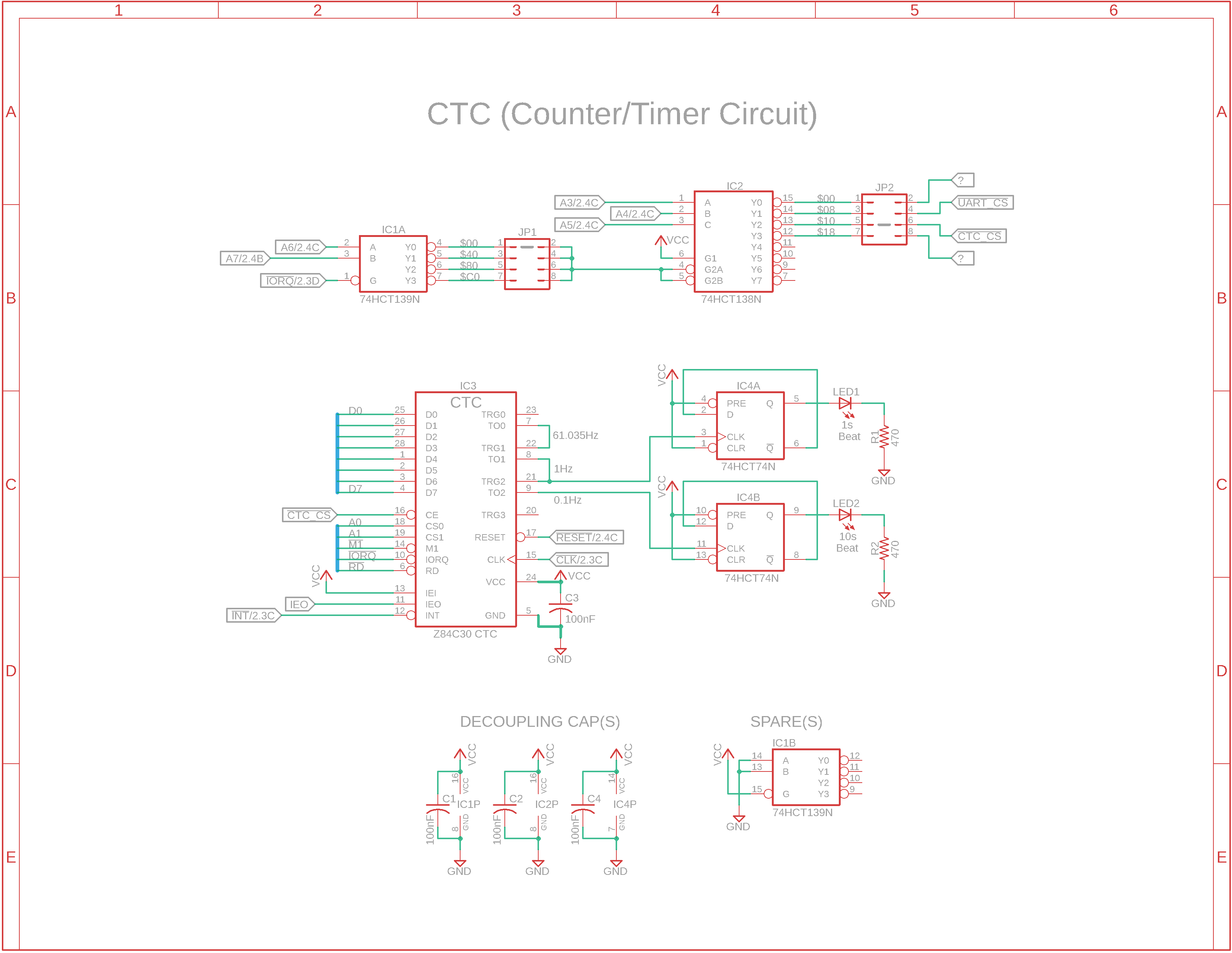
Our example In our application example, we're going to use the Zilog Z84C30xx CTC Counter/Timer Circuit to turn on an LED 30 times per second and a second LED every 1 second. Additionally, it can send an interrupt to a tiny microcontroller to play a tone every minute and flash a third LED. We could just as easily use a 555 timer in Astable Mode as shown in the upper left corner of this schematic to light the LEDs, but we want to use a device like the CTC that we can programmatically change.
DIP28 The top item in the left-adjacent Resources panel is the 28-pin Dual Inline Package (DIP28) pinout of the CTC. The item below it shows the pinout organized by function groups. Our focus in examining the Clock/Timer Circuit device are the four Channel Signals on the right side of the diagram.
Schematic: CTC and Flip-Flop The fourth item in the adjacent panel is a schematic showing a CTC with LEDs and a tone flasher. The CTC is connected to a pair of 7474 flip-flops on a single chip. When the CTC outputs assert, they are logic highs. Subsequently the first flip-flop will send a H (High) signal to output Q with a positive-going Clock pulse and the Q output will send a L (Low). When the Clock returns to L, the two outputs will retain their last state, just like a latch. We've wired Q to the D input of the first FF so that whenever the Clock transitions from H to L, the LED will illuminate before turning off as a result of the Clock transitioning to a L. The result is a brief flash but at half the receive rate. So an input of 61 highs per second would result in about 30 flashes per second.
Too flashy The flash rate would be hard to differentiate from a continuous ON condition so we fed the output of TO0 (pin 7) from Channel 0 to the input TRG1 (pin 22) of Channel 1. Channel 1's output, TO1 (pin 8) is fed to the second flip-flop's Clock input.
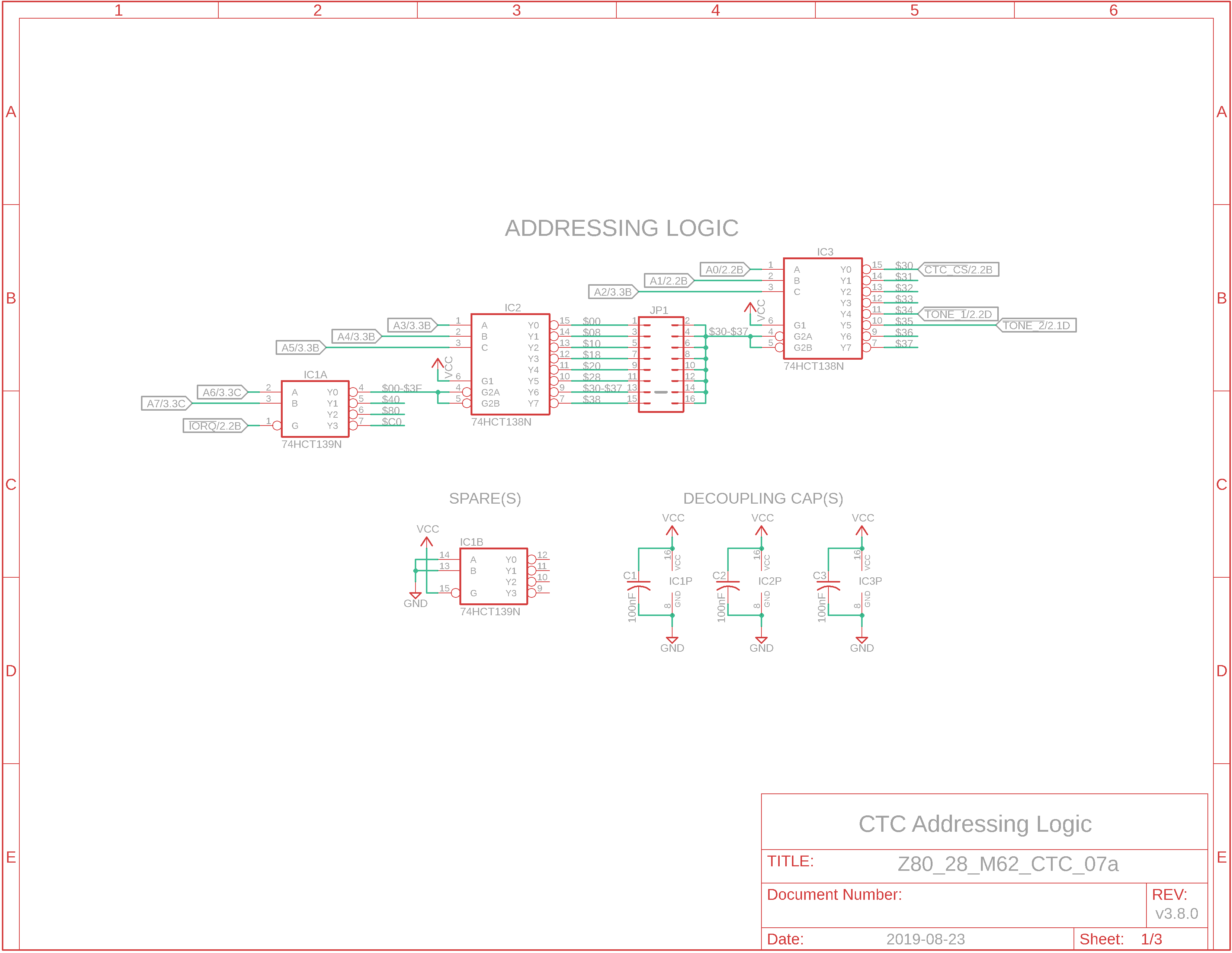
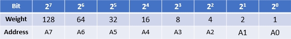
Addressing the CTC The left-most 74138 in the Addressing Logic schematic uses Z80 address line A3 as the lowest value on the A input (pin 1). You can see its binary weight in the adjacent diagram Bit Values or '138 Addresses. With a weight of 8, we know the address values will advance by multiples of 8. Pin 15 of the '138 is labeled address $00. The first address is usually always $00 so the next one on pin 14 of the '138 will be $08. In the M62-bus SBC, we've already assigned address $08 to the PC16C550 UART. We'll choose a free address block of 8 addresses starting at $30 (48 in decimal). You can see that the '138 output of pin 9 is $30. We could just connect this output pin to the CTC CE pin, but we're going to make the addressing more granular by adding another '138. Yes, there are other more efficient methods that you'll see in the Boards section but this will suffice for our current needs. Pins 13 and 14 of JP1 will be jumpered to select the address range $30 to $37. This we'll connect to the /CE Chip Enable of the CTC; any $30-$37 address will enable it. With this output feeding the enables for the second '138, we can use the A/B/C inputs to select the individual addresses. Looking at the right-most '138, we'll use pin 11 ($34) for a signal to an ATtiny85 microcontroller input to select TONE_1 to play. Optionally, we could use use pins 10 to 7 to select TONE_2 to play. Z80 address lines A0 and A1 are connected to pins 18 and 19, CS0 and CS1, respectively, of the CTC. Two address lines means two bits worth of possible addresses, that is, 4 permutations. Even though we've allocated a bank of 8 addresses starting at $30, only 4 of them will be used with the CTC: $30, $31, $32, and $33. These we'll assign to the CTC's four channels. Address $34 will enable TONE_1.
Two words for you... maybe three Each of the CTC's four independent counter/timer channels is individually programmed with two words: a channel control word and an optional time-constant word. (Note: if you don't select a time-constant word for a channel, that channel will be disabled.) There is also an Interrupt Vector word if interrupts are enabled. We'll examine the latter later. The Channel Control word: - Selects the operating mode of Counter or Timer - Enables/disables the channel interrupt - If Timer mode is selected, it sets a Prescaler which divides the system CPU Clock by 16 or 256. Example: 4MHz clock / 256 = 15,625. You can then add a time-constant word to further divide down the result. More on this in the Programming the CTC section. - Selects other parameters The Time-Constant word: - Is an 8-bit value ranging from 1 to 256
A word written to a CTC channel (e.g. CH3) is interpreted as a Channel Control word and is loaded into the channel control register, providing that bit 0 of the 8-bit word is a logic 1 (High) indicating the word is a Channel Control word and not an Interrupt Vector Register (IVR) word.
Interrupts The CTC interrupt pins (INT, IEI, and IEO) are used only if the Z80 interrupt daisy chain is implemented for Interrupt Mode 2. We won't be using them for our simple flasher but we will use them later for the tone generation. |
| NEXT PAGE: Programming the CTC => | ||
![]()
Tags: Z80 CTC, Z84C30