![]()
|
Aduino (Medium Box) M0 SBC |
| PCB Circuits (click to enlarge) | Circuits and Info |
|
Video of working Aduino 2Box M0 v1.0
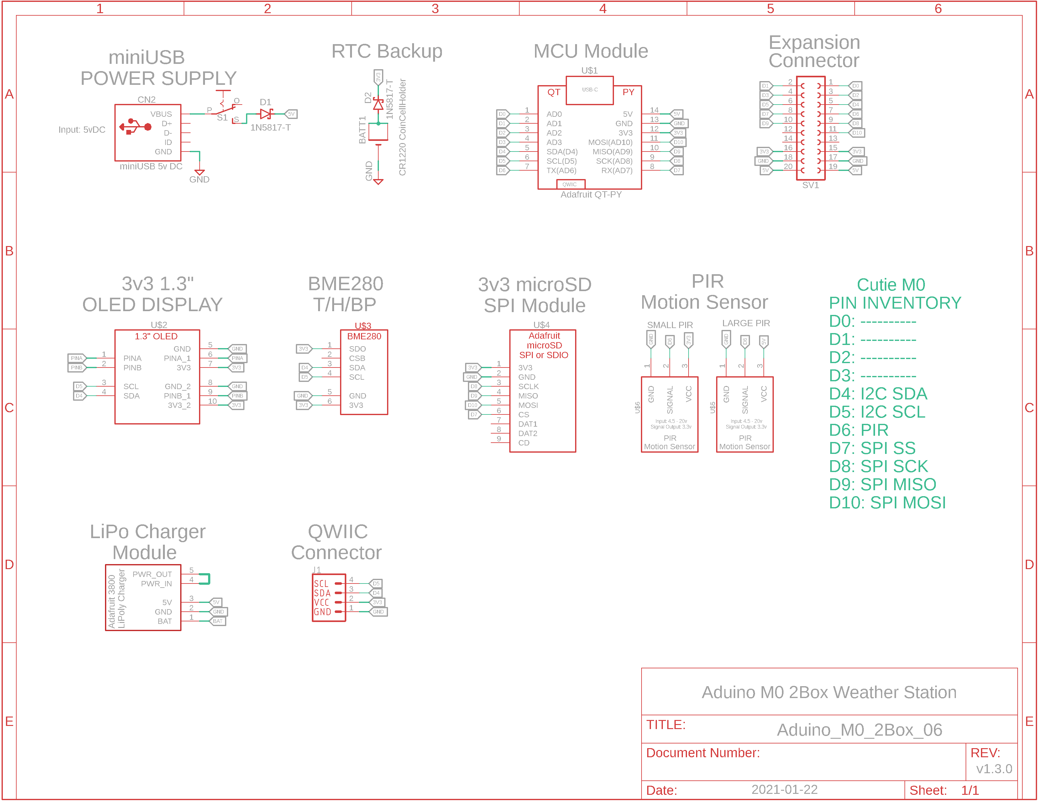
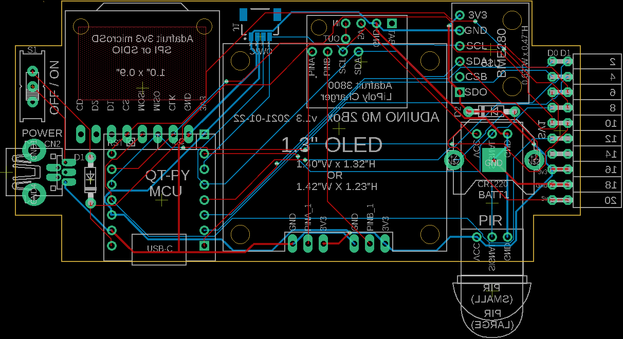
Eagle CAD: v1.3 Schematic 1
Eagle CAD: v1.3 Schematic 2
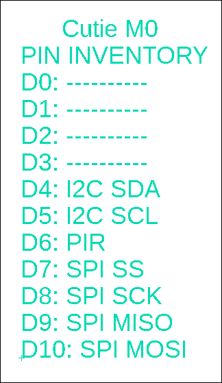
Cutie M0 Resources Allocated
(Bill of Materials, modules are not included) |
Overview The first weather station we built was comprised of an Aduino base board and an expansion board with display and sensor on it. The second weather station was similar but built as a single board computer (SBC). The third weather station was a multiboard (MBC) cube-shaped design based on the Adafruit Itsy Bitsy M4 Express. This fifth weather station will be an SBC built with the new Adafruit QT PY microcontroller. The devices on the SBC are strictly 3.3v DC but you can power the board either via USB-C to the QT PY microcontroller or via a miniUSB cable (from your PC or via a "wall wart") because I added a 3.3v DC regulator. The miniUSB cable powers the Cutie M0 in the adjacent video.
Heads-up! There are two versions of this uC board - v1.0 and v1.3. The video is from v1.0 but the Schematics are for the improved v1.3. v1.3 features: - LiPo charger with onboard 2-wire JST connector is on the bottom of the board - both mini PIR and regular PIR are supported, and should be mounted on the bottom of the board - dual right-angle female header on the right side of the SBC includes 3v3 and 5v power to other devices you may wish to attach to this dev board - 4-wire Qwiic JST connector moved to the bottom of the back of the board for connection to your I2C devices - BME280 sensor was moved away from the uC whose heat may skew the measuring
Weather Station There are several resources installed on the Cutie M0 to function as a type of weather station that can provide: - temperature, humidity, barometric pressure, dewpoint and humidex values - display of the current stats - data logging of the stats
SBC Flexibility This SBC can be expanded as a development system thanks to female header SV1 on the right side which makes available all of the 11 GPIO pins (D0 to D10) from the Cortex M0 microcontroller.
Microcontroller Resources Microchip ATSAMD21E18 Cortex M0 3v3 microcontroller: - 48MHz, 256KB Flash for program storage, 32KB dynamic SRAM for global variables. This is soooo much more than the original Atmel ATmega328 and it means you can finally run graphics on the OLED without draining all of the SRAM - native USB for programming and serial monitor debugging - I2C and SPI serial ports - 1.62v to 3.63v operation - many, many more features. Check out the Microchip datasheet or Adafruit's .pdf file on the QT PY
Adafruit Drivers & Libraries Make sure you follow the directions found at https://learn.adafruit.com/adafruit-qt-py/using-with-arduino-ide to install the drivers and libraries for their QT PY microcontroller.
I2C Devices like the 1.3" OLED and BME280 sensor utilize I2C for communication. Additional I2C devices can be connected via the tiny STEMMA QT / Qwiic JST SH 4-pin connector on the Adafruit QT PY board. You can see the cable plugged into the top left corner of the video in the adjacent column. Here are links for cables: - https://www.adafruit.com/product/4209 - https://www.adafruit.com/product/4210 -
https://www.adafruit.com/product/4401
SBC Features: - USB programming and power: Arduino IDE should be configured for "Adafruit QT PY (SAMD21)". Here is a link to installing and configuring the device - The SBC can be powered via 5v miniUSB (the QT PY converts it to 3.3v) connector or via the USB type C connector on the QT PY board - 11-pin expansion connector (D0 to D10), 5-wire power connector - 2-wire Qwiic connector to attach a LiPoly battery
Devices/Modules Included: - USB programming via USB-C connector on Adafruit QT PY microcontroller USB C connector - miniUSB power-only (no data pins) connector - 128 x 64 1.3" OLED monochrome display - microSD card module for data logging - Soft RTC. Install the RTClib library for use with the sketch. The current time is backed up with a CR1220 coin cell battery - Adafruit-compatible BME280 Temperature/Humidity/Barometric Pressure module - Motion sensing Passive Infrared (PIR) mini sensor, could be used to sense movement to enable the OLED display, etc. - Expansion via the Qwiic JST SH 4-pin I2C connector, or via the right-side dual right-angle connector
Sketches Use the QT-PY specific sketch, x_WI_Cutie-M0_j.ino, with this Aduino SAMD21 development board. You will need to modify either line 8 or 9: one of them must be commented out with "//", depending on whether your OLED uses the SSD1306 or SH1106 driver. The adjacent video shows the round-hole OLED board using the SSD1306 driver. Commonly, the oval-hole OLED board uses the SH1106 driver.
PCBs have been sent to China for fab. I will post a short video demonstrating Aduino M0 2Box operation when the boards return. |
|
|
|
![]()
Tags: Arduino-type Microcontroller, ATMega328P
![]()