|
SIO/2 UART Info 2 |
|
Resources (click to enlarge) |
||
|
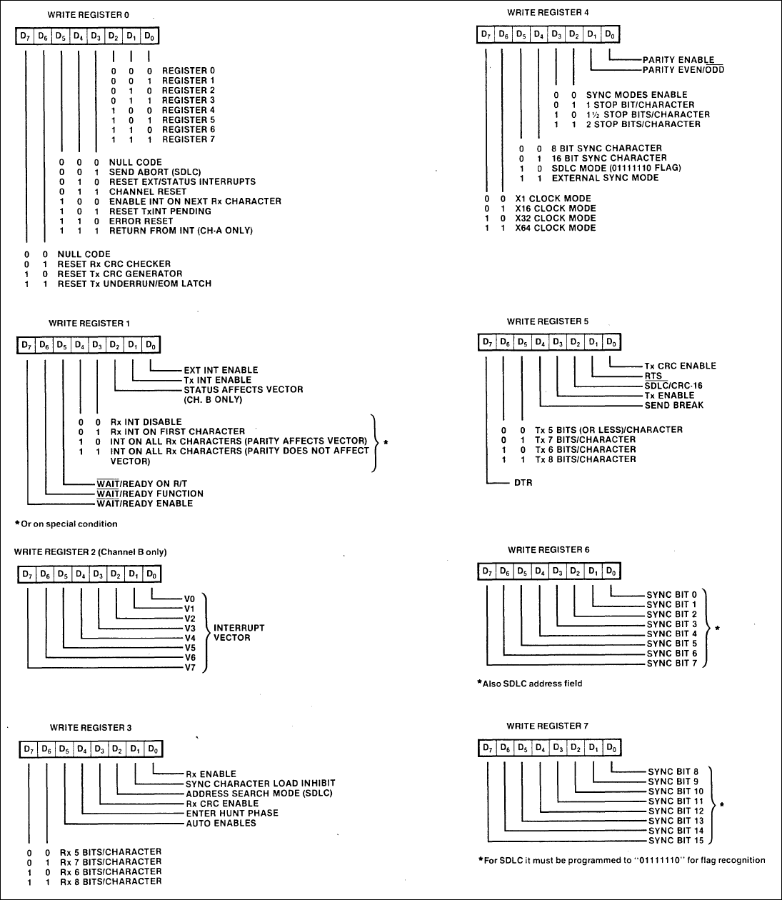
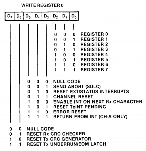
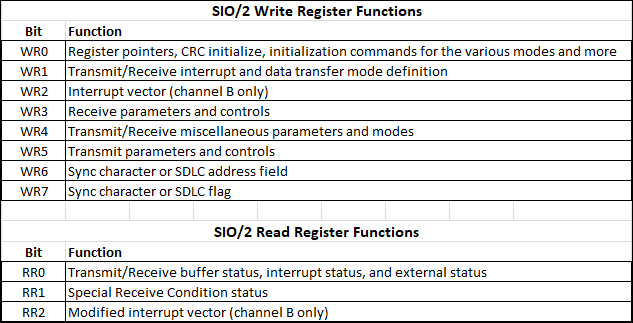
Write Registers 0 to 7:
WR0
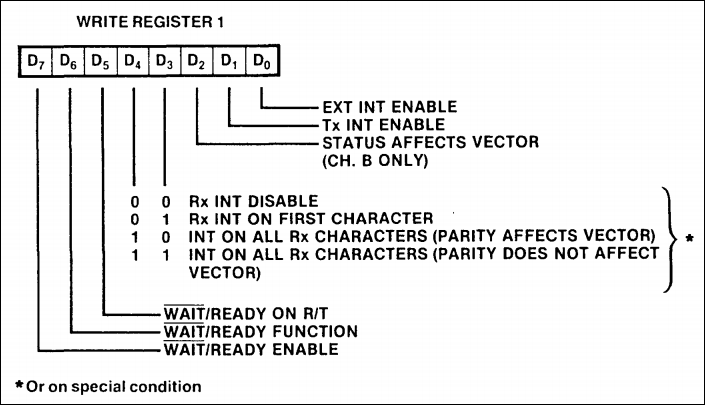
WR1: Interrupt & Data Transfer Modes
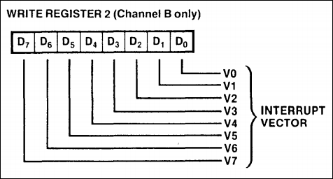
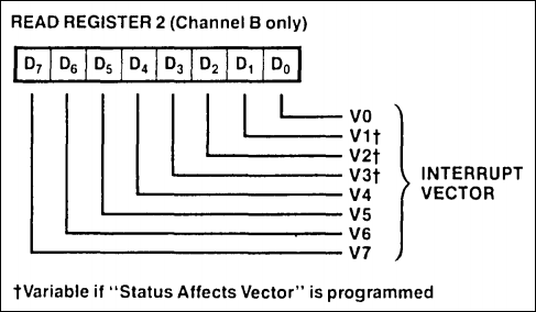
WR2: Stores the Interrupt Vector
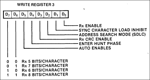
WR3: Rx Logic Control & Parameters
WR4: Tx Character Formatting
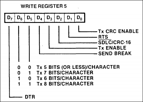
WR5: Tx Enable
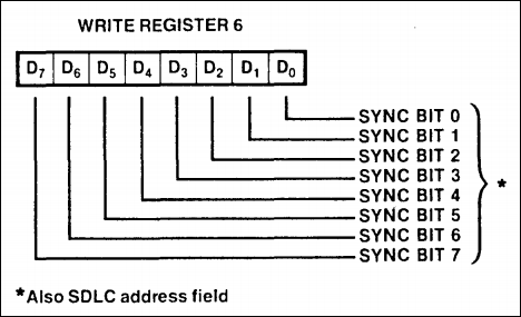
WR6: Sync Modes Only
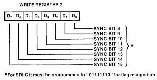
WR7: Sync Modes Only
|
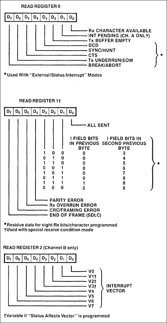
Read Registers 0 to 2:
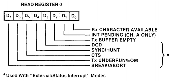
RR0
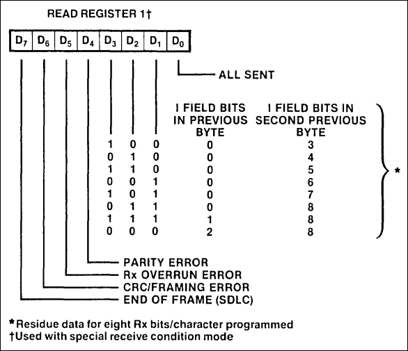
RR1
RR2
*Note that both channels do not have the same number of registers: CHA: WR0-WR1, WR3-WR7 CHA: RR0, RR2 CHB: WR0-WR7, RR0-RR2 |
SIO/2 UART Registers As you can see in the adjacent panels, there are several Write registers as well as Read registers. The thumbnail at the top of each column lists all of the registers which are then detailed below these lists. Below is a summary of the WRx and RRx registers:
PROGRAMMING THE SIO/2 According to
Zilog (page 233), the typical
program steps for Async mode are:
Initialize: - WR0: channel
reset (resets SIO). Select WR2. WR2: set the interrupt vector - WR0: reset
external/status interrupt, select WR4. WR4: Async mode, 8N1,
clock rate info - WR0: select
WR3. WR3: receive
enable, autoenables (CTS, DCD), receive character length.
An Asynchronous Receive operation begins when the
Receive Enable bit is set - WR0: select WR5. WR5: RTS, transmit enable, transmit character length, DTR. Transmission cannot begin until the Transmit Enable bit is set: WR5 D3=1 - WR0: reset external/status interrupt, select WR1. WR1: transmit interrupt enable, status affects vector, interrupt on all receive characters, disable wait/ready function, external interrupt enable.
Transfer first data byte to SIO. Program is now waiting for an interrupt from the SIO.
Data transfer and error monitoring: Z80 Interrupt Acknowledge cycle transfers RR2 to CPU. When the interrupt occurs, the interrupt vector is modified by 1) Receive character available, 2) Transmit buffer empty, 3) External/status change, and 4) Special receive condition.
If a character is received: - transfer data character to CPU - update pointers and parameters - return from interrupt
If transmitter buffer is empty, program control is transferred to one of eight ISRs: - transfer data character to SIO - update pointers and parameters - return from interrupt
If External Status changes: - transfer RR2 to CPU - perform error routines (including Break detection) - return from Interrupt
If Special Receive condition occurs: - transfer RR1 to CPU - do Special Error (such as framing error) routine - return from Interrupt
Termination: - redefine Receive/Transmit Interrupt modes - disable transmit/receive modes - update modem control outputs (such as RTS Off)
|

![]()
Tags: Z80 MBC, 1MB memory