|
SIO/2 UART Info 3 |
|
Resources (click to enlarge) |
|
|
REFERENCE DOCUMENTS
Interrupts
Z80 Applications (SIO: page 238, Appendix: page 276)
Z80 Assembly for SIO (Page 394)
Zilog SIO/2 1992 (Page 87)
|
Reference Docs There are numerous docs available on the web about Z80 interrupts many of which are just copies of each other. The four documents in the left resources panel are very helpful with my fave being Z80 Apps by J.W. Coffron. A recommendation would be to start your reading with Chapter 5 and finish with Chapter 11. It will fill in a lot of gaps you may have as a result of reading Blunk and other Internet contributors.
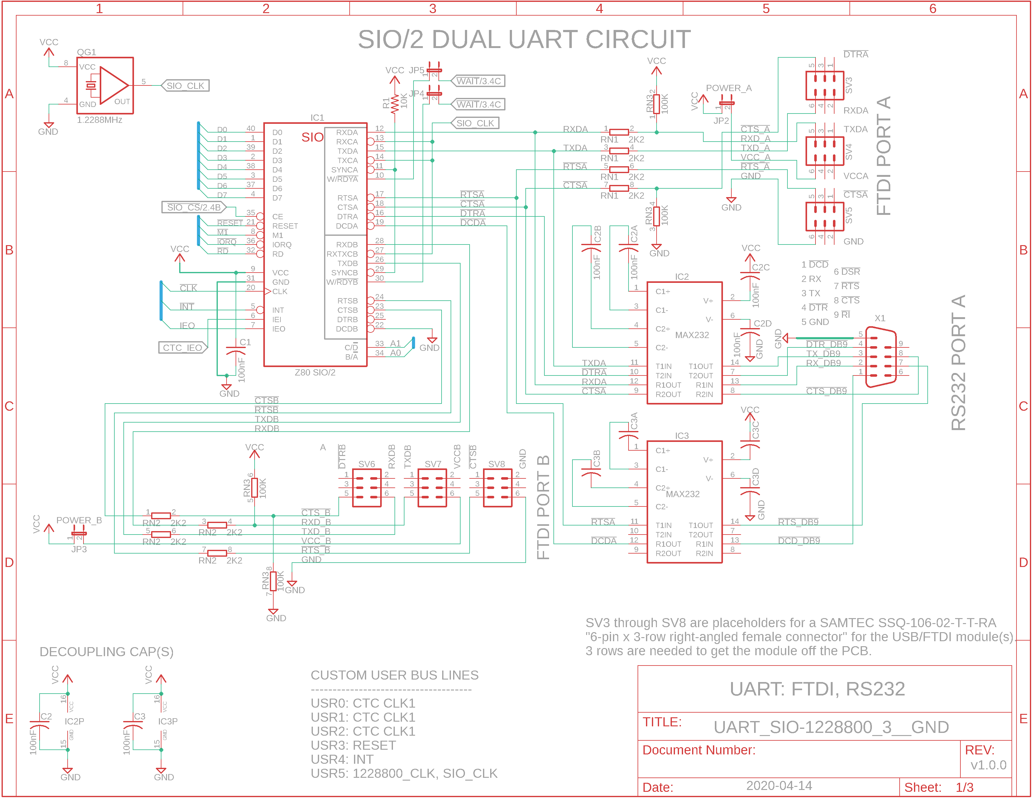
Addressing If we choose an I/O address of 38h instead of 08h as shown in the first schematic back in Info 0, then the addresses would be as follows: Pin C D : 1=Control, 0=Data. Connect to address line A1.
Pin
B A : 1=Channel B,
0=Channel A. Connect to address line A0. A1 A0 Address Lines 0 0 = Channel A Data 0 1 = Channel B Data 1 0 = Channel A Control 1 1 = Channel B Control
(I/O_0 bank decoded: 00h-3Fh. I/O block decoded: 38h - 3Fh. With just A1 and A0 address lines available, we only need 4 addresses so 38h to 3Bh will be used.)
Write (WR0-WR7) and Read Registers (RR0-RR2) Two bytes are required to write data to any register except WR0. The first byte is written to WR0 and it points to the next register to receive the next byte. This is necessary because address lines A1 and A0 are used to differentiate code that is going to channel A's control port or data port as well as channel B's control port or data port; there are no additional address lines to point to the 21 registers they comprise. That is why you will see at least two OUTs to the channel control port: the first OUT'd byte will contain the pointer to the next OUT'd byte which will contain the bit-oriented functions to configure or perform.
IN THE PAGES THAT FOLLOW WE'LL CONFIGURE THE SIO/2 UART FOR POLLING. LATER WE'LL CONFIGURE FOR INTERRUPTS.
|

![]()
Tags: SIO/2 UART