|
CIRCUIT 1-6-2: 4x4 Keypad using the 8255 PPI |
| Name | Circuit Schematics (click to enlarge) | Info |
|
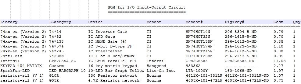
I/O: 8255 INPUT with 4x4 Keypad
(Bill of Materials)
|
Eagle CAD: 8255 PPI, 4x4 Keypad
Column:Row Keypress Matrix
|
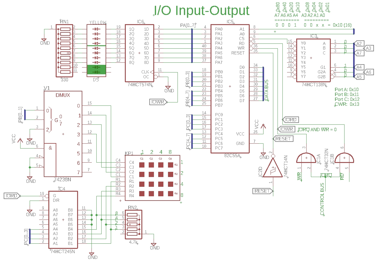
This circuit is a continuation of the previous one, 1-6-1. This time we'll look at input with the 8255 using a 4x4 keypad.
A control word of 0x81 will set ports A and B as outputs and C as input. The idea is to drive a binary pattern out one port (PB) and read what comes in on another (PC); if the value is anything other than 0, then a key was pressed. The next step would be to determine which column and row, and then somehow display it to the user. The PB and PC ports are shown as little blue buses on the left side of the schematic.
The '238 is a 3-line to 8-line non-inverting demultiplexer or demux. (A demultiplexer is a device that takes a single input line and routes it to one of several digital output lines.) If you present a binary value between 000 and 111, the output will be a 1 on the appropriate line. Examples: 000 yields a 1 on the 0 output (pin 15), and 011 puts a 1 on the 3 output (pin 12). Although the '238 has 3 inputs and 8 outputs, we will only use 2 inputs for 4 outputs to cover the 4 columns of the 4x4 matrix keypad. (Would the '239 have been a better choice for a 2-line-to-4-line device? Yes, if you can find one!)
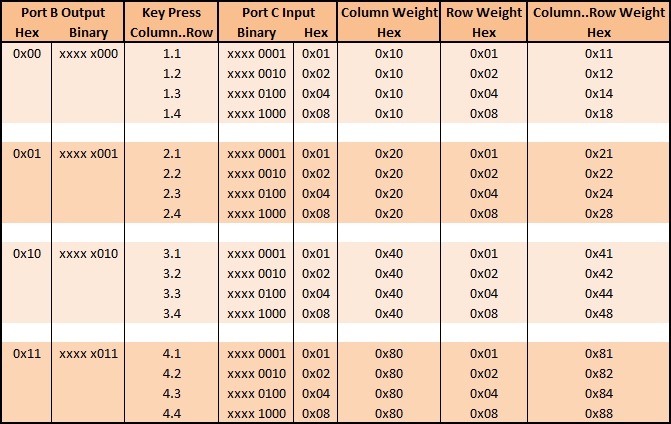
The idea is to send binary 00 out the 8255 on port B to the '238. The '238 demux will output a 1 on the 0 output which is pin 15; this is the first column. Immediately after doing so, lower part of port C is read using IORD of the '245 pins 2 to 5 for the four rows. If the value read into the 8255 is binary 0000, then no key has been pressed. If the value is 1, we know the first row has been pressed, value 2 is second row, value 4 is third row, and value 8 is fourth row. In our example, if 00 (column 1) was sent and 0001 was received, the vector is column 1 and row 1. If 00 was sent and 1000 was received, the vector is column 1 and row 4. The adjacent matrix shows you all of the key press permutations.
The program we'll use for testing this circuit later is 4x4Keypad_WeightedColRow.asm. If 00 is sent and 0000 is received, no key was pressed. The program moves on to send 01 for the second column. If no key is pressed, 10 is sent. Again, if no key is pressed 11 is sent. By cycling through all four binary combinations on port B output for the four columns and reading the key press input on lower port C for the rows, we can "vector" the column and row pressed.
Now, how do we show the user which key was pressed? We could use LEDs or an LCD panel; for now we'll use LEDs. In the next segment, we'll use the more interesting LCD. We can use 8 LEDs such that the left-most ones represent the column and the right-most ones represent the row. When the vector indicates column 0, then the row value of 1, 2, 4 or 8 is displayed as a binary value on the row LEDs. But we need to indicate the column value, too, so if we use the binary weighting of an 8-bit value, we can light up the corresponding LEDs.
Column Row 8 4 2 1 8 4 2 1 are the binary weights for column and row, left to right, respectively. 0 0 0 1 0 0 0 0 would show the first column as being chosen so we add 0x10 to the row value. 0 0 0 1 0 0 0 1 indicates first column and first row. 0 0 1 0 0 0 0 0 Adding 0x20 to the row value gives us the second column. 0 0 1 0 0 1 0 0 0x24 indicates second column and third row. 1 0 0 0 1 0 0 0 0x88 indicates fourth column and fourth row. This is detailed in the adjacent screenshot, Column:Row Keypress Matrix. This is our feedback to the user.
The clock has to be set high enough (500Hz) that IORD will occur during the key press. Set the clock speed too low and the key press may be missed.
Test Your Circuit Visit Z80 IO Output Test II to test your circuit. It contains useful info and a video demo. |
![]()